Posts

Showing posts from October, 2017

PELTON,KAPLAN AND FRANCIS TURBINE

Image
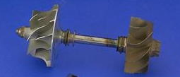
PELTON TURBINE :The pelton wheel turbine is impulse turbine,which is of tangential flow type. In this turbine energy at the inlet of turbine is in the form of kinetic energy.This is used for low flow rate and high head.Pressure through out remains atmospheric. The main parts of pelton turbine are: 1)Nozzle or flow controlling:It controls the rate of flow as per requirement of variable power. 2)Runner or bucket:It is of shape double hemispherical seperated by splitter which devides water without shock. 3)Casing:Casing has not hydraulic function.It only prevent water from splashing. 4)Braking jet:To stop the runner in smallest possible time.                                                       Fig:Pelton wheel turbine runner FRANCIS TURBINE :Francis turbine is reaction turbine.In this type of turbine at inlet is in the form of both kinetic as well as pressure energy.The runner is completely enclosed that is it is air tight.As the water flows a part of pres

piston and piston ring

Image
                                   PISTON It is a cylindrical component which reciprocates inside engine cylinder.It is movable wall.It transmits power produce to crankshaft through connecting rod.It provide seal for the gasses. Material : For piston desired properties are: a)Uniform expansion at high temperature b)Low weight so aluminium alloy is best choice                                                                       PISTON RING            On piston there are gooves which hold piston rings.This include compression ring or gas ring,wiper ring and oil ring.There prime function is to seal the gas and circulate lubricating oil. compression ring or gas ring :it is located closest to piston hesd.It’s function is to seal the gasses during high pressure.When  the gas is burnt huge pressure is generated.Which can leak to casing. Wiper ring: It is piston ring with tapered face.It is used to further seal the combustion gass.It wipes out cylinder wall to remove exc

COMBINED BRAKING SYSTEM AND ANTI LOCKING BRAKING SYSTEM

Image
                        COMBINED BRAKING SYSTEM It is preferred that both front and rear brake are applied simultaneously but most of driver can not use them simultaneously in good way.Combined braking system is interlocked braking system.It gives easy comfortable and controlled braking system.                It reduces braking distance and increases stability during braking. WORKING PRINCIPLE                                                                    fig:CBS schematic diagram                                                                                                                 main components are as follows: (1)calliper (2)delay valve (3)pressure control valve    The rear hydraulic brake is provided with pessure control valve and delay valve is provided with front wheel.While applying the rear brake hydraulic pressure from master cylinder is applied to pressure control valve and delay valve. This pushes the piston in rear brake calipe

supercharger and turbocharger

Image
   comparison of tubocharger and supercharger Turbocharger-A turbocharger uses the exhaust gas for its energy.With the help of turbine exhaust gas rotates the compressor and thus by forcing extra air in the combustion chamber it increases engine efficiency.It is used in race cars,alrge diesel engines. The basic advantage of using a turbocharger is that you get more power output for the same size of engine                                             fig:turbine and compressor on same shaft Supercharger-In contrast to tubocharger supercharger is mechanically driven by engine. there are two types of supercharger (a)Positive displacement (b)Dynamic pump pros of tubocharger 1.significant boost in power 2.increases fuel economy cons of turbocharger 1.due to turbo lag it takes time to boost 2.Economic for large size engine pros of supercharger 1.Assures immediate boost. 2.Zero lag 3.Easier to install 4.good power even at low rpm 5.can be used for any size eng

cooling tower

Image
A cooling tower is a specialized heat exchanger in which air and water are brought into direct contact with each other in order to reduce the water's temperature.A small amount of water evaporates taking away heat which is being circulated  Types of cooling towers 1.Classification based on air flow generation method    (a)Natural draft-Due to temperature difference there is density difference.Due to density difference there exists buyancy. warm air is less dense than drier air at the same pressure. This moist air buoyancy produces an upwards current of air through the tower.Fresh cool air is drawn from bottom.   . (b)Mechanical draft-Uses external source for forced  air flow.For this power driven motor is utilized 2.Classification based on heat trabnsfer method    (a)Dry cooling towers    (b)wet cooling towers    (c) Fluid coolers

octane rating vs cetane rating

Image
Octane rating Definition -The octane rating of fuel is defined as percentage by volume of iso-octane in the mixture of iso-octane and normal heptane,which exactly matches the intensity of fuel in standard engine under a set of standard operating conditions.mainly applied in case of SI engine. 1. Octane rating is also called antiknocking rating because it signifies the ability to resist knocking when used in engine. 2.Higher octane number fuel permits higher compression ratio.The higher the octane number the better is the resistance of Gasoline to combustion prematurely, known as knocking. 3.It is the measure of resistance of gasoline against detonation or pre-ignition of fuel . 4.Higher the octane number, better the quality of petrol, and hence the vehicle gives higher efficiency. 5.Used in SI engine                                      Cetane rating Definition -The cetane rating of fuel is defined as percentage by volume of normal cetane in the mixture of normal c